Range AFM Disabler: Blue vs Red vs Green LED
Range disabler blue vs red represents a significant choice for General Motors vehicle owners who seek to personalize their cockpit while maintaining full V8 engine power and reliability. This exhaustive technical guide from gadon.store examines the cosmetic variations of these indicator lights and their relationship with the health of the engine. By understanding these options, you will discover how to eliminate transmission shudder and prevent catastrophic lifter failure in your truck or SUV without flashing the factory software.
Gadon™ AFM/DFM Disabler
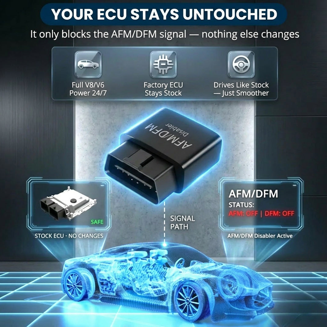
This compact OBD2 plug-in device keeps the engine of General Motors vehicles operating in full V8 mode. It prevents rough shifting and torque converter shudder while saving you from expensive lifter repair bills. The module does not reprogram the engine control unit. The team at Gadon.store is ready to help you confirm compatibility for your specific vehicle today.
Why Proper Engine Mode Selection is Crucial? A Direct Impact on V8 Performance and Engine Lifespan
Selecting the correct mode for the engine of your vehicle is the foundation of long term durability and consistent performance. When a vehicle transitions between V8 and V4 modes, the internal components experience uneven thermal cycles and mechanical stress. Using a Gadon AFM/DFM disabler correctly ensures the engine stays in full V8 mode, delivering smooth and lag-free performance while extending the lifespan of the engine by preventing costly lifter failures caused by constant cylinder switching. Without a proper module, the frequent deactivation of cylinders leads to various mechanical issues that compromise the integrity of the vehicle.
The following factors illustrate why maintaining full cylinder operation is essential for your vehicle:
- Uniform Wear: All sixteen valves and lifters operate at the same frequency, ensuring even distribution of oil and heat.
- TCC Stability: The torque converter clutch does not have to hunt for the correct slip rate, which eliminates the annoying shudder felt during highway cruising.
- Instant Response: The driver experiences immediate throttle response because the engine control unit does not need to re-engage dormant cylinders during acceleration.
- Oil Consumption Prevention: Constant cylinder deactivation can lead to oil blow-by and increased consumption over time.
A Detailed 3-Step Guide to Using the AFM Disabler for GM Owners
Installing a performance module from Gadon.store is a straightforward process that requires zero mechanical expertise or specialized tools. This plug and play system interacts directly with the diagnostic port to communicate with the engine control unit in real time. Following this protocol ensures that the vehicle remains in its high performance state from the moment the ignition starts until the trip concludes. The process takes less than ten seconds and provides immediate results that the driver can feel during the first mile of travel.
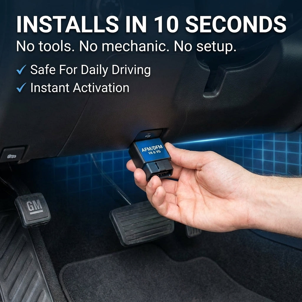
Step 1: Unbox and Locate the OBD2 Port
First, locate the OBD2 diagnostic port inside the truck or SUV of General Motors, usually found under the dashboard on the driver side. It is essential to ensure that the engine of the vehicle is completely turned off before proceeding with the physical installation. Clearing the area around the port ensures a clean connection and prevents any interference with the electrical pins of the module during the insertion process. Most owners find the port near the hood release latch or the steering column base.
Step 2: Plug the Device Securely
Take the Gadon™ AFM/DFM Disabler and push it firmly into the port. There are no tools required for this operation. You will notice the indicator lights flash, confirming it has successfully connected to the ECU or engine control unit. This visual confirmation is vital because it indicates that the module is receiving power and is ready to transmit the keep-alive signal to the vehicle computer. Ensure the module is seated deeply enough so that it does not vibrate loose during heavy off road use or highway driving.
Step 3: Start the Engine and Experience Full V8 Power
Start the engine and begin your journey. The device instantly blocks the cylinder deactivation signals without rewriting the factory software. You can now drive normally, experiencing immediate smoother throttle response, no lag, and consistent V8 power on every drive. Whether you are towing a heavy trailer or cruising on the interstate, the vehicle will stay in eight cylinder mode indefinitely. This transition provides a seamless driving experience that factory settings simply cannot match due to fuel economy regulations.
Need Help Checking Vehicle Compatibility? Gadon.store is Ready 24/7
In just 2 minutes, our expert team can confirm if the Gadon™ AFM/DFM Disabler fits your exact model.
Advanced Tips: Understanding AFM/DFM on GM Vehicles
Active Fuel Management and Dynamic Fuel Management are technologies designed by General Motors to improve fuel efficiency by shutting down specific cylinders during light load conditions. While these systems appear beneficial on a window sticker, they introduce significant complexity and potential points of failure within the valvetrain. Understanding how these systems interact with the physical hardware of the engine allows owners to make informed decisions about vehicle protection and performance enhancement. Gadon.store provides these insights to help drivers avoid expensive engine rebuilds.
How Cylinder Deactivation Causes Lifter Failure
The constant switching between V4 and V8 modes creates uneven wear on the active lifters. Special collapsing lifters are used in these engines to allow the valves to stay closed during deactivation. Over time, the locking pins within these lifters can fail due to oil aeration or mechanical fatigue. This leads to premature lifter failure, bent pushrods, and costly engine rebuilds that can exceed five thousand dollars in total costs. By maintaining full cylinder operation, you ensure that the oil pressure remains consistent and the lifters stay in their locked and functional position at all times.
Eliminating Transmission Shudder at Cruising Speeds
Many drivers experience a noticeable shudder or vibration at speeds between thirty five and sixty miles per hour. This phenomenon is often caused by the torque converter clutch attempting to compensate for the reduced torque output of the engine when it is in V4 mode. By keeping the engine in full cylinder mode, the Gadon module balances the torque delivery to the transmission. This eliminates the awkward gear searching behavior and vibration entirely, providing a much smoother ride for both the driver and the passengers during long trips.
Troubleshooting Common Issues with the AFM Disabler Module
While the Gadon™ AFM/DFM Disabler is designed for seamless operation, occasional questions may arise regarding its status lights or impact on the electrical system of the truck. Technical transparency is a core value at Gadon.store, and providing clear solutions to common user experiences is part of our commitment to excellence. Most issues are related to the vehicle power supply or the diagnostic port fuse rather than the module itself. Understanding these simple troubleshooting steps can save you time and ensure that your engine remains protected against cylinder deactivation risks at all times.
- Why are the lights on the device not turning on? The solution is to check the OBD2 fuse of the vehicle, which is often shared with the cigarette lighter circuit. If the fuse is blown, the port will not provide power to the Gadon module.
- Will the module drain the battery of my truck? The device draws a very minimal amount of power on standby mode. However, if you plan to leave the truck parked and undriven for several weeks, the team recommends unplugging the module to ensure the battery remains at full charge.
- Do I need to unplug it before taking it to the dealership? Yes, simply unplug the Gadon disabler before your scheduled service visit. Since it leaves zero trace on the ECU and does not flash the software, the factory warranty remains fully intact during and after the visit.
- Does the LED color affect performance? No, the choice between blue, red, or green LEDs is purely cosmetic and does not change the effectiveness of the cylinder deactivation bypass.
Range Disabler LED Color and Package Comparison

When evaluating range disabler blue vs red, it is important to realize that these variations are designed to match the interior lighting of your vehicle. Whether you prefer the cool look of blue or the aggressive appearance of red, the internal hardware remains consistent. The following table provides a detailed breakdown of the various options and packages available at Gadon.store to help you maximize the performance and aesthetics of your General Motors vehicle.

| Feature or Package | Blue LED Module | Red LED Module | Gadon™ Performance |
|---|---|---|---|
| Primary Benefit | Disables AFM/DFM | Disables AFM/DFM | Max V8 Protection |
| Visual Style | Cool Blue Glow | High Contrast Red | Professional Indicator |
| Interior Match | Chevy/GMC Dash | Custom/Sport Looks | Universal Compatibility |
| ECU Impact | Zero Trace | Zero Trace | Zero ECU Flashing |
| Single Unit Price | Competitive Rate | Competitive Rate | Starting at $99.99 |
| Bulk Discount | Available | Available | Up to 25 Percent Off |
| Warranty Support | Standard | Standard | 90-Day Full Refund |
| Technical Help | Limited | Limited | Expert 24/7 Hotline |
Which Gadon™ AFM/DFM Disabler Package is Right for You? Expert Advice
Selecting the right package depends on the number of General Motors vehicles in your household or business fleet. At Gadon.store, we offer tiered solutions to ensure that every driver can protect their engine investment while enjoying significant savings. Every purchase includes our 90 day guarantee and free shipping. You can use a discount code to get an extra ten percent off today when you secure your vehicle. Investing in a multi pack is a wise decision for families who own both a truck and an SUV equipped with cylinder deactivation technology.
- For Personal Use: For owners of a single daily driver truck, the 1 Pack Gadon™ Disabler is the perfect choice. You will feel the V8 difference immediately upon your first drive.
- For Multi Vehicle Owners: If you own a Silverado and your spouse drives a Tahoe, the 2 Packs option is ideal, offering a fifteen percent discount for a dual vehicle upgrade.
- For Fleets and Workshops: For commercial fleets or professional mechanics, the 3 Packs option offers the best value with a twenty five percent discount, ensuring all work trucks are protected against lifter failure.
Gadon™ AFM/DFM Disabler
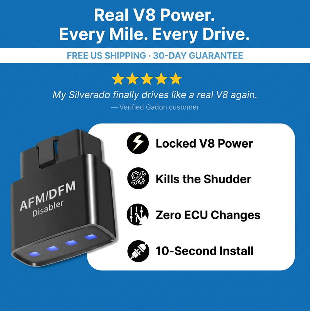
This smart module blocks the V4 mode of your vehicle, preventing sudden hesitations and devastating lifter collapses. It is easy to install and preserves the health of your engine while protecting the factory warranty. Unlock the true potential of the V8 power plant in your truck today.
Quick FAQs on Gadon AFM/DFM Disablers
Navigating the world of automotive performance modules can lead to several technical questions. We have compiled the most frequent inquiries from our community of over fifty thousand customers to provide you with clear and concise answers regarding the use and benefits of our technology. Whether you are concerned about your warranty or the long term health of your lifters, these answers provide the clarity you need to proceed with confidence. Our team is dedicated to providing high quality information that empowers vehicle owners to take control of their engine performance.
- Will it void my GM warranty or trigger a Check Engine Light? No, the module does not reprogram the ECU. Simply unplug it before a dealership visit, and it leaves zero trace. It will not trigger any diagnostic trouble codes.
- Will it fit my specific truck model? Yes, the module is compatible with over ninety General Motors lines from 2005 onwards, including Silverado, Sierra, Tahoe, Yukon, and Escalade models.
- Will this actually save my engine from expensive repairs? Absolutely, by preventing the mechanical stress of cylinder deactivation, you avoid the common causes of lifter failure and pushrod damage.
- When will I feel the difference while driving? Most drivers report an immediate improvement in throttle response and a smoother gear transition within the first mile of driving.
- How hard is the installation process? It takes less than ten seconds and requires no tools. If you can plug in a phone charger, you can install this device successfully.
Need Help Checking Vehicle Compatibility? Gadon.store is Ready 24/7
In just 2 minutes, our expert team can confirm if the Gadon™ AFM/DFM Disabler fits your exact model.
Protect Your GM Engine and Regain Full V8 Power with Gadon.store
At Gadon.store, we provide a reliable, plug and play solution that unleashes the true V8 potential of your engine while protecting it from expensive lifter failures. We are committed to high quality performance modules, zero ECU tracing, and excellent customer support for every driver. Upgrade your ride and drive with confidence knowing your vehicle is running at its full capacity. Call our support hotline now at +1 813-408-1627 or order directly from our website to secure your vehicle today!
Disclaimer: The instructions in this article are based on practical experience with GADON STORE products. Always ensure your vehicle is parked safely before interacting with the OBD2 port. Please contact contact@gadon.store for detailed support regarding your specific GM model compatibility. Note: The guidance and prices in this article are for reference at the time of publishing and are subject to change.